Chirp Signal Generation
Table of contents
Introduction
The Chirp Signal Generation Project aims at providing basic code to generate Frequency Modulated Continuous Wave (FMCW) on the SensEdu Shield using the Arduino Giga R1. The projects provides two types of waveform for Linear Frequency Modulation (LFM): sawtooth and triangular.
A signal whose frequency varies over time is called chirp. Chirp signals are encountered in numerous fields, like radar and sonar systems, telecommunications, signal processing and more. Further information about potential applications are provided in the documentation of our FMCW ranging project. The following figures show an example of a chirp with frequency range between 100Hz and 10kHz, and the spectrogram of the same chirp, respectively.
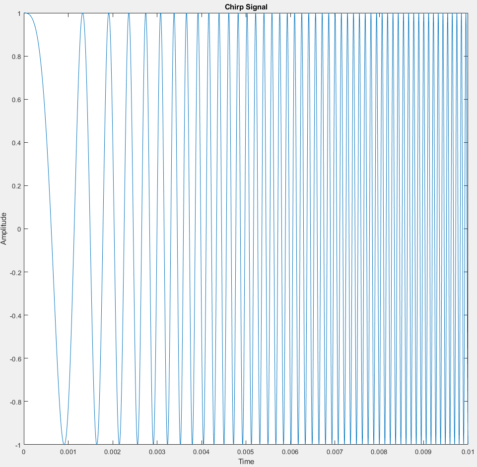
Chirp signal sweeping from 100Hz to 10kHz
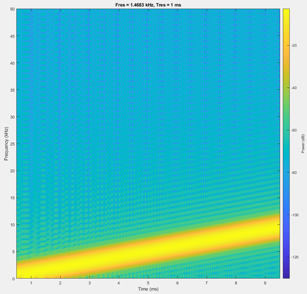
Spectrogram of a chirp sweeping from 100Hz to 10kHz
Chirp Generation Function
Arduino does not provide any built-in chirp signal function. There are workarounds using MATLAB’s built-in chirp function but our idea was to create this signal directly in Arduino with the SensEdu library.
The generate_sawtooth_chirp and generate_triangular_chirp functions both calculate the values to generate a sawtooth chirp and triangular chirp respectively and copy these values to the DAC’s buffer.
void generate_sawtooth_chirp(uint16_t* array)
void generate_triangular_chirp(uint16_t* array)
Parameters
uint16_t* array: A pointer to an array where the generated chirp signal will be stored.
Description
A full sine period is four mirrored copies of the same quarter wave, so only 0-90 degrees has to be stored. The chirp generating functions build the waveform from a lookup table:
lut_sineis a LUT containing the values of a quarter sine wave. It holds90 * LUT_RESOLUTIONentries, soLUT_RESOLUTIONis the number of points stored per degree. A larger value results in a more detailed LUT, which in turn increases the precision of the chirp values which will be calculated.chirp_valueholds the sample currently being computed, which is written straight into the DAC buffer.
The following steps describe how the function was implemented:
Step 1: Generate the quarter-wave LUT:
// Generate the quarter-wave sine LUT
    for (int i = 0; i < 90 * LUT_RESOLUTION; i++) {
        phase_deg = (float)i * 90.0 / (90 * LUT_RESOLUTION); // Phase angle in degrees
        phase_rad = phase_deg * PI_F / 180.0; // Phase angle to radians
        lut_sine[i] = sin(phase_rad-PI_F/2); // Store sine value in the LUT
    }
Step 2: Calculate the instantaneous phase of the chirp signal and wrap between 0-360 degrees:
for (int i = 0; i < samples_int; i++) {
        phase_rad = 2.0 * PI_F * (0.5 * chirp_rate * i / fs + START_FREQUENCY) * i / fs; // Phase angle in radians
        phase_deg = phase_rad * 180.0 / PI_F; // Phase angle to degrees
        phase_deg_wrapped = fmod(phase_deg, 360.0); // Wrap phase angle to 0-360 degrees
Step 3: Calculate the value of the chirp using a quadrant-based approach, then scale and offset to 12-bit and write it into the DAC buffer:
        if (phase_deg_wrapped <= 90) {
            chirp_value = lut_sine[(int)(phase_deg_wrapped)* LUT_RESOLUTION+1] * 2048 + 2048;
        } else if (phase_deg_wrapped <= 180) {
            chirp_value = -lut_sine[(int)(180.0 - phase_deg_wrapped) * LUT_RESOLUTION+1] * 2048 + 2048;
        } else if (phase_deg_wrapped <= 270) {
            chirp_value = -lut_sine[(int)(phase_deg_wrapped - 180.0) * LUT_RESOLUTION+1] * 2048 + 2048;
        } else {
            chirp_value = lut_sine[(int)(360.0 - phase_deg_wrapped)* LUT_RESOLUTION+1] * 2048 + 2048;
        }

        array[i] = (uint16_t)chirp_value;
    }
For the triangular modulation, only the first half of the buffer is swept; the second half mirrors it to form the down-sweep.
    // Mirror the up-sweep to form the down-sweep
    for (int i = half_samples; i < samples_int; i++) {
        array[i] = array[samples_int - i-1];
    }
In this configuration, the first value of the chirp signal array is 0 (or 0 V in amplitude at DAC output). This initial value can be changed by modifying lut_sine.
Main code
Check out the DAC section for more information on the DAC library and different DAC related functions.
The Chirp_SawtoothMod.ino and Chirp_TriangularMod.ino files contain the main code to generate the chirp signal, send the chirp signal to the DAC and enable the DAC.
The code contains the following user settings to adjust the chirp signal:
CHIRP_DURATION: The period of the chirp signal in secondsSTART_FREQUENCY: The start frequency of the chirp signal in HzEND_FREQUENCY: The end frequency of the chirp signal in Hz
A very important variable in the main code is the sampling frequency fs. Based on the Nyquist-Shannon sampling theorem, fs needs to be at least double the maximum frequency (or end frequency) of the chirp signal.
Keep in mind this sampling frequency will also be the DAC’s output frequency in the SensEdu_DAC_Settings function.
fs needs to be at least 2*END_FREQUENCY in order for the chirp signal to be generated properly.
The samples_int is an integer representing the amount of samples for one period of the chirp signal. This value also represents the memory size in the SENSEDU_DAC_BUFFER and SensEdu_DAC_Settings functions.
The values of the chirp are printed in the serial monitor.
// Print the chirp signal LUT
    Serial.println("start of the Chirp LUT");
    for (int i = 0 ; i < samples_int; i++) { // loop for the LUT size
        Serial.print("value ");
        Serial.print(i+1);
        Serial.print(" of the Chirp LUT: ");
        Serial.println(lut[i]);
    }