Timers Peripheral
Timers provide hardware support for generating delays, issuing periodic peripheral triggers for sampling rates, and producing PWM signals.
Errors
The main timer error code prefix is 0x10xx. See how to display errors in your Arduino sketch here.
An overview of possible errors for timers:
0x1000: No Errors0x1001: Unexpected delay value. Minimum possible is 1ns0x1002: Wrong ADC selected. No timer associated with the specified ADC0x1003: Selected unsupported TIMx0x1004: Unexpected generic frequency setting0x1005: Unexpected ADC frequency setting. Recommended limit is 1MHz, refer to SensEdu_ADC_Settings for more details0x1006: Unexpected DAC frequency setting. Recommended limit is 15MHz, refer to SensEdu_DAC_Settings for more details0x1007: Unexpected PWM duty cycle. Must be in a range from 0 to 1000x1008: TIM8 initialization attempt while TIM8 is running. Configuration is possible only for disabled timer0x1009: TIM8 Unexpected CCR channel. Possible options are:CCR1,CCR2,CCR3orCCR4
An overview of critical errors. They shouldn’t happen in normal user case and indicate some problems in library code:
0x10A0: Timer frequency calculations failed0x10A1: Driver has been stuck in a delay indefinitely
Functions
SensEdu_TIMER_DelayInit
Initializes the timer used for microsecond delays. Call it once in the setup before using delays.
void SensEdu_TIMER_DelayInit();
All delay functions are blocking. The CPU cannot execute other tasks during the delay.
SensEdu_TIMER_Delay_us
Pauses program execution for a specified duration in microseconds (blocking delay).
void SensEdu_TIMER_Delay_us(uint32_t delay_us);
Parameters
delay_us: Delay duration in microseconds. Maximum: \(4,294,967,295 \text{us}\).
Notes
- For
delay_us\(\leq\) \(1000\text{us}\), the function internally switches toSensEdu_TIMER_Delay_ns(), to offer more precise timings with software overhead compensation.
SensEdu_TIMER_Delay_ns
Pauses program execution for a specified duration in nanoseconds (blocking delay).
This is an experimental function. Read the notes carefully.
void SensEdu_TIMER_Delay_ns(uint32_t delay_ns);
Parameters
delay_ns: Delay duration in nanoseconds. Maximum: \(4,294,967,295 \text{ns}\).
Notes
- For
delay_ns\(\gt\) \(1000\text{us}\), the function internally switches toSensEdu_TIMER_Delay_us()to avoid potential 32-bit overflow in theNS_TO_TICKS(ns)macro. - The lowest achievable timer resolution on STM32H747 MCU is ~\(4.17\text{ns}\), calculated as: \(\text{tick} = 1/240\text{MHz} \times 10^9 \approx4.17\text{ns}\). Delays are therefore multiples of this tick, approximately: \(4\text{ns}\), \(8\text{ns}\), \(13\text{ns}\), \(17\text{ns}\), etc.
- In theory, delays shorter than about \(250\text{ns}\) are not achievable because the configured frequencies are close to the MCU system clock frequency. These delays become overpowered by the software overhead. Executing the function itself takes roughly \(60-120\) CPU cycles, which corresponds to ~\(125-250\text{ns}\) on a \(480\text{MHz}\) core. In practice, including software overhead, the effective minimum delay is closer to \(550\text{ns}\).
- To account for software overhead, a hardcoded compensation of \(550\text{ns}\) is applied. Additionally, any requested delays below this threshold are automatically raised to \(550\text{ns}\). The reasons for this exact number are explained in the compensation section.
Examples
Blink_Delay
Blinks a LED using microsecond delays.
- Include the SensEdu library and declare the LED pin (
LED_BUILTINin this case) - Initialize the timer with
SensEdu_TIMER_DelayInit() - Configure the LED pin as an
OUTPUTusingpinMode() - Use alternating calls to
SensEdu_TIMER_Delay_us()anddigitalWrite()in the main loop to toggle the LED state.
On Arduino GIGA R1 the built-in LED is active-low: LOW = on, HIGH = off.
#include "SensEdu.h"

uint8_t led = LED_BUILTIN;

void setup() {
    SensEdu_TIMER_DelayInit();

    pinMode(led, OUTPUT);
    digitalWrite(led, LOW);
}

void loop() {
    SensEdu_TIMER_Delay_us(500000);
    digitalWrite(led, HIGH);
    SensEdu_TIMER_Delay_us(500000);
    digitalWrite(led, LOW);
}
Developer Notes
Timer occupation
Peripheral timers (ADC/DAC) are hidden, automatically configured and require no user involvement.
Timer allocation:
- TIM1: ADC1 sampling
- TIM3: ADC2 sampling
- TIM6: ADC3 sampling
- TIM2: Delays
- TIM4: DAC sampling
- TIM8: PWM
Avoid reusing occupied timers. Refer to STM32H747 Reference Manual to find available timers. Be aware, future updates will assign dedicated timers to each ADC/DAC separately, which may occupy your custom timer.
Frequency settings
Timer frequency is dependent on 3 parameters:
- Clock Frequency \((CLK)\)
- Prescaler \((PSC)\): CLK divider
- Period \((ARR)\): Register containing the value up to which the count proceeds
The CLK signal is derived from the APB1 and APB2 Timer Clocks, each running at 240MHz.
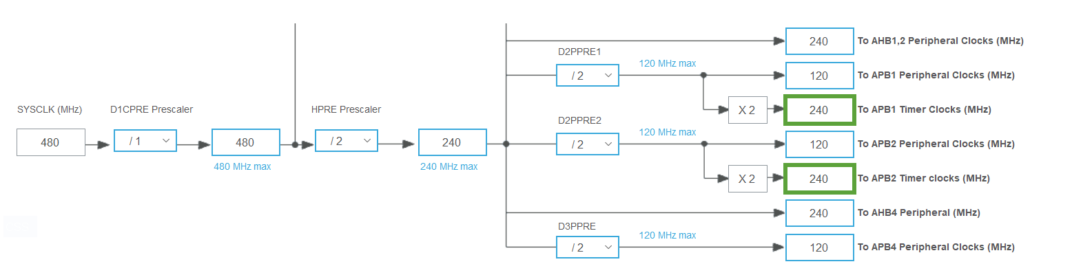
Prescaler is set to its minimum value to achieve the finest frequency adjustments, resulting in a step size of \(\frac{1}{120\text{MHz}} \approx 8.33\text{ns}\).
| ARR | Period | Frequency |
|---|---|---|
| 1 | 16.7ns | 60MHz |
| 2 | 25.0ns | 40MHz |
| 3 | 33.3ns | 30MHz |
| 4 | 41.7ns | 24MHz |
| 5 | 50.0ns | 20MHz |
When a user specifies a frequency for a DAC or ADC, the target value is automatically rounded to the nearest achievable frequency dictated by the timer’s step. The lower target frequency, the higher the achievable precision.
Software Overhead Compensation in Nanosecond Delays
Software execution adds an unavoidable overhead, which becomes noticeable for very small delays in the range of hundreds of nanoseconds. To measure this, a simple test was performed:
SensEdu_TIMER_Delay_ns(1);
digitalWrite(pin, HIGH);
SensEdu_TIMER_Delay_ns(1);
digitalWrite(pin, LOW);
This test is not fully precise, since digitalWrite() itself introduces an additional delay. However, because digital I/O is a typical use case for these delays, the results are considered representative.
The following figure shows the resulting waveform for a set delay of \(1\text{ns}\), followed by a summary table with measurement results for various delays.

| Set Delay | Actual Delay | Software Overhead |
|---|---|---|
| 1ns | 546ns | 545ns |
| 250ns | 788ns | 538ns |
| 1000ns | 1537ns | 537ns |
| 5000ns | 5522ns | 522ns |
Based on these results, the rounded average execution overhead is estimated as \(550\text{ns}\). This value is defined in timer.c as the macro DELAY_CPU_OVERHEAD_NS and is automatically subtracted from the requested nanosecond delay. The figure below shows a requested delay of \(5000\text{ns}\): without compensation (black) and with compensation (blue). While compensation is applied, the delay averages ~\(5004\text{ns}\).
