DAC Peripheral
A DAC (Digital-to-Analog Converter) generates an analog waveform from 12-bit digital values transferred to the peripheral via DMA with fixed timer sampling.
The DAC is configured for 12-bit values, with a maximum value of \(2^{12} - 1 = 4095\) (0x0FFF). All DAC LUT values must remain within this 12-bit range, otherwise the output may saturate. This differs from ADC peripherals, which work with 16-bit samples.
The STM32H747 features one 12-bit DAC module with two available channels internally wired to ultrasonic transducers:
- Speaker TX1: connected to the first channel (
DAC_CH1) onDAC0pin - Speaker TX2: connected to the second channel (
DAC_CH2) onDAC1pin
In many examples the lookup table (LUT) is used to transfer the data via DMA to the DAC peripheral. After the data is loaded into DAC internal registers, the wave generation can work in 3 different modes:
- Continuous mode: LUT table is transferred continuously to the DAC circularly
- Burst mode: LUT table is transferred specified number of cycles
- Single mode: LUT table is transferred single time (Burst mode with cycles = 1)
Errors
The main DAC error code prefix is 0x40xx. See how to display errors in your Arduino sketch here.
An overview of possible errors for DAC:
0x4000: No errors0x4001: Input settings arenull0x4002: DAC already enabled before initialization - unexpected behaviour0x4003: Passed DAC channel is neitherDAC_CH1norDAC_CH20x4004: Selected sampling frequency exceeds maximum (~15MHz)0x4005: Different sampling frequencies selected forDAC_CH1andDAC_CH2. This is not allowed, since both channels are connected to the same sampling timer0x4006: Invalid DMA address or buffer size0x4007: InSENSEDU_DAC_MODE_BURST_WAVE,burst_nummust be ≥ 1
An overview of critical errors. They shouldn’t happen in normal user case and indicate some problems in library code:
0x40A0: DMA Underrun interrupt flag was raised: currently selected trigger is driving DAC channel conversion at a frequency higher than the DMA service capability rate (read more in section 27.4.8 of Reference Manual)0x40A1: Driver has been stuck in a delay indefinitely
Structs
SensEdu_DAC_Settings
DAC configuration structure.
typedef struct {
    DAC_Channel* dac_channel;
    uint32_t sampling_freq;
    uint16_t* mem_address;
    uint16_t mem_size;
    SENSEDU_DAC_MODE wave_mode;
    uint16_t burst_num;
} SensEdu_DAC_Settings;
Fields
dac_channel: Selects the DAC channel (DAC_CH1orDAC_CH2)sampling_freq: Specified DAC sampling frequency. Maximum value is around 15MHzmem_address: DMA buffer addressmem_size: DMA buffer sizewave_mode:SENSEDU_DAC_MODE_CONTINUOUS_WAVE: Continuous modeSENSEDU_DAC_MODE_BURST_WAVE: Burst modeSENSEDU_DAC_MODE_SINGLE_WAVE: Single mode
burst_num: Number of LUT cycles forSENSEDU_DAC_MODE_BURST_WAVEmode
Notes
burst_numis not ignored only forSENSEDU_DAC_MODE_BURST_WAVEmode.
Functions
SensEdu_DAC_Init
Configures DAC clock and initializes the peripheral with specified settings (channel, sampling frequency, waveform, etc.)
void SensEdu_DAC_Init(SensEdu_DAC_Settings* dac_settings);
Parameters
dac_settings: DAC configuration structure
Notes
- Initializes associated DMA and timer.
SensEdu_DAC_Enable
Enables DAC module, wave transmission starts.
void SensEdu_DAC_Enable(DAC_Channel* dac_channel);
Parameters
dac_channel: DAC Channel instance
Notes
- There is no separate
EnableandStartfunction as for ADC.
SensEdu_DAC_Disable
Deactivates DAC peripheral.
void SensEdu_DAC_Disable(DAC_Channel* dac_channel);
Parameters
dac_channel: DAC Channel instance
SensEdu_DAC_GetBurstCompleteFlag
Returns the burst status flag of the DAC channel. When transfer is finished, it returns true.
bool SensEdu_DAC_GetBurstCompleteFlag(DAC_Channel* dac_channel);
Parameters
dac_channel: DAC Channel instance
Returns
burst_completeflag:trueindicates finished burst transfer
SensEdu_DAC_ClearBurstCompleteFlag
Clears the burst status flag of the DAC channel to its default value false.
void SensEdu_DAC_ClearBurstCompleteFlag(DAC_Channel* dac_channel);
Parameters
dac_channel: DAC Channel instance.
Examples
Examples are organized incrementally. Each builds on the previous one by introducing only new features or modifications. Refer to earlier examples for core functionality details.
If you want to see complete examples, visit \examples\ directory or open them via Arduino IDE by navigating to File → Examples → SensEdu.
Each example uses a LUT with specified (12-bit) values and size. An example of defining a sine wave of 64 samples is shown in the following code snippet:
const SENSEDU_DAC_BUFFER(buffer_name, buffer_size) = {...};
The first parameter of SENSEDU_DAC_BUFFER is the user-defined name to be used in the program code while the second parameter is the size of the LUT.
Always use SENSEDU_DAC_BUFFER macro to define arrays/LUTs for the DAC. This macro automatically handles all buffer requirements for cache coherence, regardless of the selected size. For details, visit the MPU Configuration section.
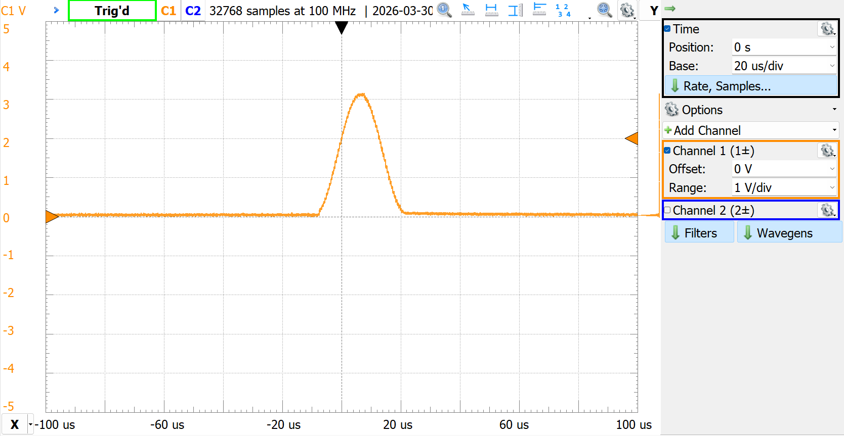
DAC_Single_Sine
Transmitting a single instance of a predefined LUT with sine waveform.
- Include SensEdu library
- Declare DAC Buffer and initialize it with sine LUT
- Initialize the
SensEdu_DAC_Settingsstruct with DAC parameters. - Initialize
SensEdu_DAC_Initwith created struct - Enable wave transmission
SensEdu_DAC_Enable
#include <SensEdu.h>

const uint16_t sine_lut_size = 64;
const SENSEDU_DAC_BUFFER(sine_lut, sine_lut_size) = {
    0x0000,0x000a,0x0027,0x0058,0x009c,0x00f2,0x0159,0x01d1,
    0x0258,0x02ed,0x038e,0x043a,0x04f0,0x05ad,0x0670,0x0737,
    0x0800,0x08c8,0x098f,0x0a52,0x0b0f,0x0bc5,0x0c71,0x0d12,
    0x0da7,0x0e2e,0x0ea6,0x0f0d,0x0f63,0x0fa7,0x0fd8,0x0ff5,
    0x0fff,0x0ff5,0x0fd8,0x0fa7,0x0f63,0x0f0d,0x0ea6,0x0e2e,
    0x0da7,0x0d12,0x0c71,0x0bc5,0x0b0f,0x0a52,0x098f,0x08c8,
    0x0800,0x0737,0x0670,0x05ad,0x04f0,0x043a,0x038e,0x02ed,
    0x0258,0x01d1,0x0159,0x00f2,0x009c,0x0058,0x0027,0x000a
};

#define DAC_SINE_FREQ       32000                           // 32kHz
#define DAC_SAMPLE_RATE     DAC_SINE_FREQ * sine_lut_size   // 64 samples per one sine cycle

DAC_Channel* dac_ch = DAC_CH1;
SensEdu_DAC_Settings dac_settings = {
    .dac_channel = dac_ch,
    .sampling_freq = DAC_SAMPLE_RATE,
    .mem_address = (uint16_t*)sine_lut,
    .mem_size = sine_lut_size,
    .wave_mode = SENSEDU_DAC_MODE_SINGLE_WAVE,
    .burst_num = 0
};

void setup() {
    SensEdu_DAC_Init(&dac_settings);
}

void loop() {
    SensEdu_DAC_Enable(dac_ch);
    delay(100);
}
Notes
- In this example wave is sent every 100ms.
- If you put only
SensEdu_DAC_Enablein setup, then the wave will be transmitted only once when you power up the board, so it could be easily missed. If you want to see it with an oscilloscope, you could reset firmware by pressingRSTbutton once on Arduino (do not press two times in succession, you will clear MCU firmware this way) - Internally
SENSEDU_DAC_MODE_SINGLE_WAVEadjusts toSENSEDU_DAC_MODE_BURST_WAVEwithburst_num= 1
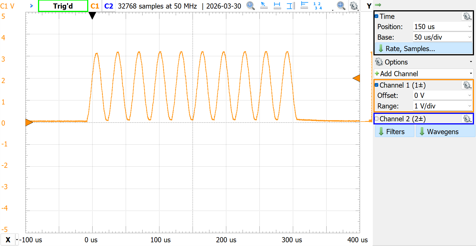
DAC_Burst_Sine
Transmitting a specified number of cycles of a predefined LUT with sine waveform, creating bursts.
- Follow single wave example
Send_DAC_Single_Sine - Change
wave_modetoSENSEDU_DAC_MODE_BURST_WAVE - Specify
burst_numto desired cycle number
// DAC configuration struct
    .wave_mode = SENSEDU_DAC_MODE_BURST_WAVE,
    .burst_num = 10
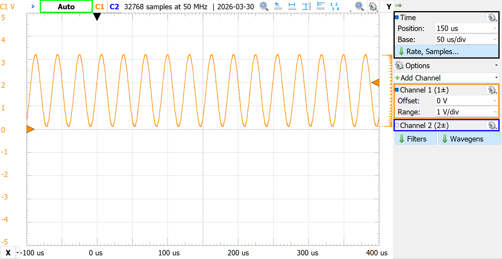
DAC_Const_Sine
Transmitting a constant sine wave with predefined LUT.
- Follow single wave example
Send_DAC_Single_Sine - Change
wave_modetoSENSEDU_DAC_MODE_CONTINUOUS_WAVE - Enable DAC once in setup with
SensEdu_DAC_Enable
// DAC configuration struct
    .wave_mode = SENSEDU_DAC_MODE_CONTINUOUS_WAVE,
    ...

void setup() {
    SensEdu_DAC_Init(&dac_settings);
    SensEdu_DAC_Enable(dac_ch);
}

void loop() {
    // nothing
}
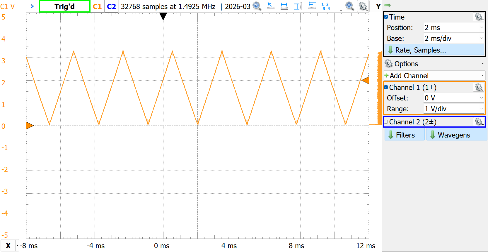
DAC_Variable_Wave
Transmitting wave constantly with LUT changes during the program execution (run-time modifications). For this specific example we use small DAC buffer (4 elements) to generate a triangular wave across whole 12-bit region.
- Include SensEdu library
- Declare DAC Buffer and initialize it with any values
- Initialize the
SensEdu_DAC_Settingsstruct with DAC parameters for constant wave - Initialize
SensEdu_DAC_Initwith created struct and enable the wave transmissionSensEdu_DAC_Enable - Modify LUT to create triangular shape by incrementing or decrementing each LUT element in a loop. When any value reaches 0 or 4095, change direction with
increment_flag
#include <SensEdu.h>

static uint8_t increment_flag = 1; // run-time modification flag

const size_t lut_size = 4;
static SENSEDU_DAC_BUFFER(lut, lut_size) = {
    0x0000,0x0001,0x0002,0x0003
};

DAC_Channel* dac_ch = DAC_CH1;
SensEdu_DAC_Settings dac_settings = {
    .dac_channel = dac_ch,
    .sampling_freq = 64000*16, // ~1MHz sampling rate
    .mem_address = (uint16_t*)lut,
    .mem_size = lut_size,
    .wave_mode = SENSEDU_DAC_MODE_CONTINUOUS_WAVE,
    .burst_num = 0
};

void setup() {
    SensEdu_DAC_Init(&dac_settings);
    SensEdu_DAC_Enable(dac_ch);
}

void loop() {
    // modify lut
    for (uint16_t i = 0; i < lut_size; i++) {
        if (increment_flag) {
            lut[i]++;
        } else {
            lut[i]--;
        }
    }

    // Revert direction when 12-bit limits are reached
    if (lut[0] == 0x0000) {
        increment_flag = 1;
    }
    if (lut[lut_size-1] == 0x0FFF) {
        increment_flag = 0;
    }
}
DAC_2CH
Since the DAC module has 2 channels, it is possible to use both of them simultaneously if needed. Initializing two channels in code means having two DAC structures for each:
#define DAC_SAMPLING_RATE_HZ   (64000)

DAC_Channel* dac_ch1 = DAC_CH1;
DAC_Channel* dac_ch2 = DAC_CH2;

SensEdu_DAC_Settings dac1_settings = {
    .dac_channel = dac_ch1,
    .sampling_freq = DAC_SAMPLING_RATE_HZ,
    .mem_address = (uint16_t*)lut1,
    .mem_size = lut1_size,
    .wave_mode = SENSEDU_DAC_MODE_BURST_WAVE,
    .burst_num = dac_cycle_num
};

SensEdu_DAC_Settings dac2_settings = {
    .dac_channel = dac_ch2,
    .sampling_freq = DAC_SAMPLING_RATE_HZ,
    .mem_address = (uint16_t*)lut2,
    .mem_size = lut2_size,
    .wave_mode = SENSEDU_DAC_MODE_BURST_WAVE,
    .burst_num = dac_cycle_num
};
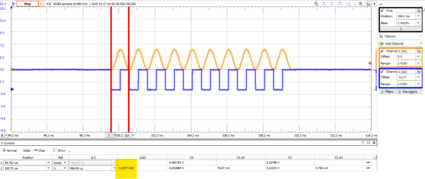
In this example, lut1 contains samples for one cycle of a sine wave, and lut2 contains samples for one cycle of a square wave. Both look-up-tables contain 64 samples each. We generate 10 cycles of sine and square wave with frequency of 1kHz with the sampling frequency of 64kHz. The following figure shows the output on an oscilloscope.
There are a couple of things to consider in order to achieve desired frequency wave at the DAC. Basically, there are two things that affect the final wave frequency:
- Waveform LUT: The contents define how many samples the DAC receives per one DMA transfer
- Sampling Frequency: How many samples per second the DAC outputs
Consider the LUT containing one cycle of a square wave, a “shape” which is split across 64 samples. By controlling the sampling rate, the final frequency can be defined:
\[f_{wave} = \frac{f_{\text{sampling}}}{N_{\text{LUT samples per cycle}}}\]Let’s assume we want to achieve \(1\text{kHz}\) square wave, that means that DAC must output samples with a rate of:
\[f_{\text{sampling}} = 64 \text{ samples} \times 16\text{kHz} = 64\text{kHz}\]#define DAC_SAMPLING_RATE_HZ (64000)
const size_t lut_size = 64;
const SENSEDU_DAC_BUFFER(lut, lut_size) = {
0x0000,0x0000,0x0000,0x0000,0x0000,0x0000,0x0000,0x0000,
0x0000,0x0000,0x0000,0x0000,0x0000,0x0000,0x0000,0x0000,
0x0000,0x0000,0x0000,0x0000,0x0000,0x0000,0x0000,0x0000,
0x0000,0x0000,0x0000,0x0000,0x0000,0x0000,0x0000,0x0000,
0x0ff0,0x0ff0,0x0ff0,0x0ff0,0x0ff0,0x0ff0,0x0ff0,0x0ff0,
0x0ff0,0x0ff0,0x0ff0,0x0ff0,0x0ff0,0x0ff0,0x0ff0,0x0ff0,
0x0ff0,0x0ff0,0x0ff0,0x0ff0,0x0ff0,0x0ff0,0x0ff0,0x0ff0,
0x0ff0,0x0ff0,0x0ff0,0x0ff0,0x0ff0,0x0ff0,0x0ff0,0x0ff0
};
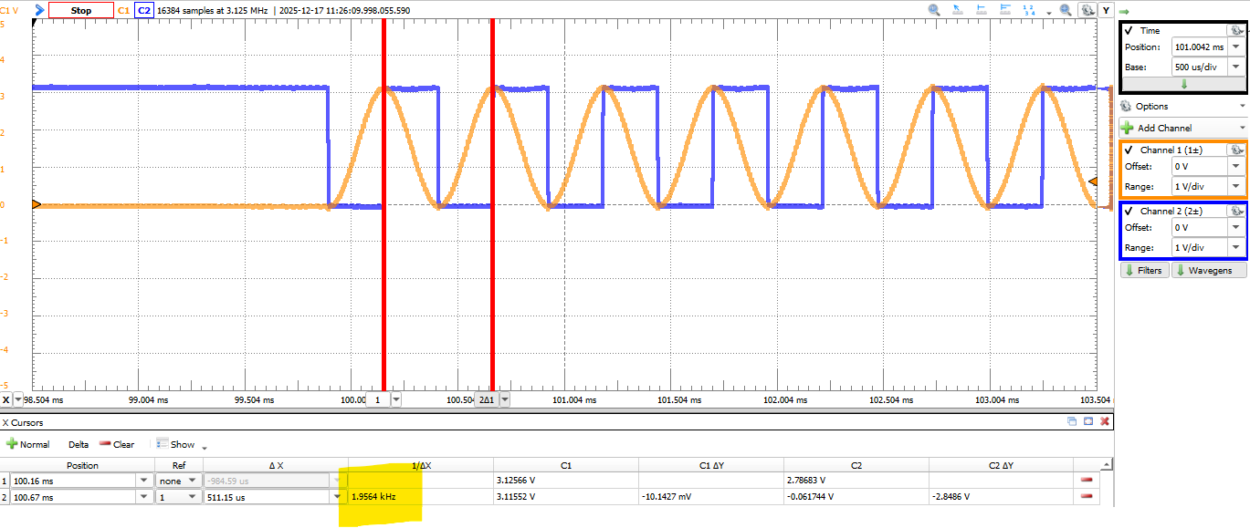
If the sampling rate is doubled, then DAC outputs samples twice as fast, resulting in a \(2\text{kHz}\) wave without any changes to the LUT.
#define DAC_SAMPLING_RATE_HZ   (128000)

const size_t lut_size = 64;
const SENSEDU_DAC_BUFFER(lut, lut_size) = {
    0x0000,0x0000,0x0000,0x0000,0x0000,0x0000,0x0000,0x0000,
    0x0000,0x0000,0x0000,0x0000,0x0000,0x0000,0x0000,0x0000,
    0x0000,0x0000,0x0000,0x0000,0x0000,0x0000,0x0000,0x0000,
    0x0000,0x0000,0x0000,0x0000,0x0000,0x0000,0x0000,0x0000,
    0x0ff0,0x0ff0,0x0ff0,0x0ff0,0x0ff0,0x0ff0,0x0ff0,0x0ff0,
    0x0ff0,0x0ff0,0x0ff0,0x0ff0,0x0ff0,0x0ff0,0x0ff0,0x0ff0,
    0x0ff0,0x0ff0,0x0ff0,0x0ff0,0x0ff0,0x0ff0,0x0ff0,0x0ff0,
    0x0ff0,0x0ff0,0x0ff0,0x0ff0,0x0ff0,0x0ff0,0x0ff0,0x0ff0
};
Otherwise, keeping the sampling rate at the same \(64\text{kHz}\) and making the LUT represent 2 cycles of a wave in the same 64 samples (or 1 cycle per 32 samples). Again, it doubles the wave frequency:
\[f_{wave} = \frac{64\text{kHz}}{32 \text{ samples}} = 2\text{kHz}\]#define DAC_SAMPLING_RATE_HZ (64000)
const size_t lut_size = 32;
const SENSEDU_DAC_BUFFER(lut, lut_size) = {
0x0000,0x0000,0x0000,0x0000,0x0000,0x0000,0x0000,0x0000,
0x0000,0x0000,0x0000,0x0000,0x0000,0x0000,0x0000,0x0000,
0x0ff0,0x0ff0,0x0ff0,0x0ff0,0x0ff0,0x0ff0,0x0ff0,0x0ff0,
0x0ff0,0x0ff0,0x0ff0,0x0ff0,0x0ff0,0x0ff0,0x0ff0,0x0ff0
};
If you decide to keep multiple wave cycles in one LUT, be mindful about it in burst and single wave modes, since one burst “cycle” in settings represents one LUT. If you want to achieve 10 wave cycles you need burst of 5, because one LUT cycle contains 2 wave cycles.
When working with 2 channels simultaneously, the sampling rate is forced to be the same by the DAC driver. Since the sampling frequency is the same, to achieve different wave frequencies between two channels, you can only change the LUT.
Developer Notes
Output Buffer
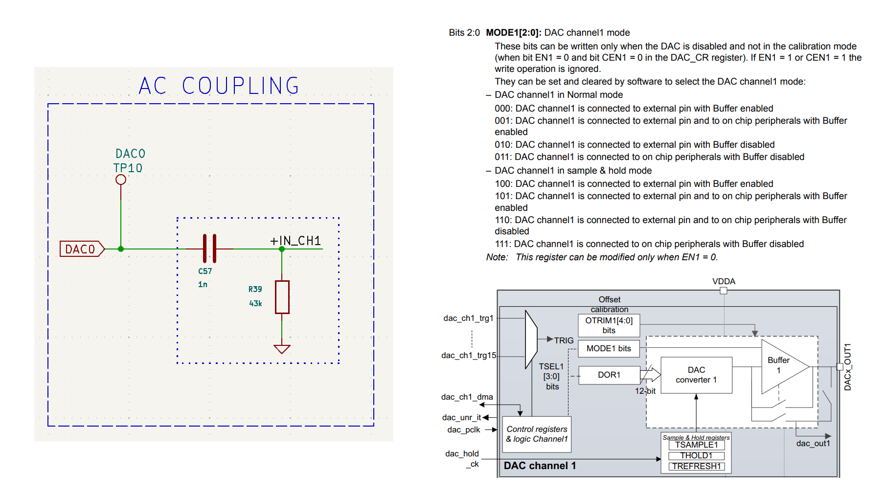
AC coupling circuit right after the DAC takes more current than DAC normally can deliver, resulting in a signal attenuation. To drive bigger currents, the internal buffer right at the DAC output can be enabled by setting the MCR register to 0b000 (page 1109 of the Reference Manual).
DMA Streams
Each DAC channel occupies one DMA Stream:
- Channel 1: DMA1_Stream2
- Channel 2: DMA1_Stream3
Avoid reusing occupied DMA streams. Refer to STM32H747 Reference Manual to find free available streams.
Cache Coherence
When using DAC with DMA, you need to be aware of cache coherence problems. By default, the processor’s data cache (D-Cache) boosts memory access speed, but this can conflict with DMA operations. The DMA controller transfers data directly between memory and peripherals without CPU involvement. The issue arises when CPU interact with memory handled by DMA, the processor might read stale data from cache instead of updated memory used by DMA, as it is not aware of DMA transfers.
You can think that it shouldn’t be a problem for DAC, since the data is written from memory to peripheral, CPU doesn’t read anything. The problem arises, because default Arduino MPU (Memory Protection Unit) configuration enables write-back policy for writing operations. There are two possible policies:
- Write-through policy (WT): Data is written to both cache and memory
- Write-back policy (WB): Data is written to the cache first
That means if you use WB policy and update DAC buffer (waveform), DMA may not see updates unless the cache is explicitly cleaned.
There are two ways to fix this:
- Cache Cleaning
- MPU Configuration
SensEdu uses MPU Configuration for the DAC.
Cache Cleaning
After updating the DAC buffer, explicitly clean the cache to force writes to physical memory. Use the CMSIS function SCB_CleanDCache_by_Addr(mem_addr, mem_size) with the following parameters:
mem_addr: Memory address of the DAC buffermem_size: Memory size in bytes
// Update Buffer
for (uint16_t i = 0; i < buf_size; i++) {
    buf[i] = i;
}
// Clean Cache and Start DAC
SCB_CleanDCache_by_Addr((uint16_t*)buf, sizeof(buf));
SensEdu_DAC_Enable(DAC_CH1);
The cache cleaning procedure applies to the entire cache line. Therefore, it is essential to align your DAC buffer to the cache line and ensure its size is a multiple of the cache line size. For the STM32H747, the cache line is 32 bytes long and is defined in the macro __SCB_DCACHE_LINE_SIZE. For a uint16_t array, this means the number of elements must be a multiple of 16 (each element is 2 bytes). For example. valid sizes include 16, 32, 64, etc. Alignment is achieved using the __attribute__ directive:
const uint16_t buf_size = 128; // multiple of __SCB_DCACHE_LINE_SIZE/2
__attribute__((aligned(__SCB_DCACHE_LINE_SIZE))) uint16_t buf[buf_size];
MPU Configuration
To avoid manual cache maintenance, configure the MPU to mark the DAC buffer’s memory region as non-cacheable. This bypasses the cache entirely, ensuring DMA always accesses physical memory.
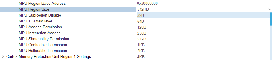
First, you need to ensure the correct buffer size. It must be a power of two (starting at 32 bytes) and aligned to its size. From STM32CubeMX MPU screenshot, you can see an example of proper sizes.
The SensEdu library automates this with the SENSEDU_DAC_BUFFER(name, user_size) macro:
name: Variable name to access the buffer later in codeuser_size: buffer size in uint16_t
const uint16_t buf_size = 50;
SENSEDU_DAC_BUFFER(buf, buf_size);
for (uint16_t i = 0; i < buf_size; i++) {
    buf[i] = i;
}
The SENSEDU_DAC_BUFFER macro allows any user-defined size. The library internally adjusts it to meet MPU requirements.
After buffer allocation, during DMA_DACInit() the library configures the MPU region using internal function LL_MPU_ConfigRegion() to enforce non-cacheable and non-bufferable memory region.